Flow sensors measure the flow rate in volume per unit of time, for example in liters/minute. They safely and reliably handle monitoring tasks as well as precise measuring tasks, for example for volume flow measurement, in dosing monitoring or compressed air consumption measurement.
EGE flow sensors for liquid media have a detection range that depends on the diameter of the measuring tube. Devices with small diameters work particularly well with small flow rates, correspondingly large quantities are well detected by sensors with large diameters.
The characteristics of EGE flow sensors are given in l/min or ml/min. Sensors with an adjustment potentiometer for monitoring limit values have an LED display. Devices with a numerical display have push buttons and can be programmed individually.
EGE flow sensors for gaseous media provide a signal proportional to the air mass flow. Simple devices are suitable for operation in atmospheric ambient conditions. For consumption measurement, complex Venturi and dynamic pressure systems are used in addition to calorimetric systems. The flow rate is indicated by an LED display or a numerical display.
Talk to our experts for flow and flow sensor technology about your request. Feel free to contact us directly by phone via e-mail or contact form.
Contact usThe EGE-inline flow controllers with digital display monitor flow rates in the range of 0,05...100 l/min and display the flow rate digitally. They feature front panel buttons used to call functions and modify settings. The application area includes all areas of flow monitoring and measuring, in which a flow display is desired.
The SDN 552/554 series is based on the thermodynamic principle, heat is created in a measuring pipe and absorbed by the passing medium. The dissipated heat quantity is a measurement for the flow speed. A microprocessor processes this data, calculates the flow rate quantity and displays the result in liters/minutes in a 3-digit, 7-segment display.
The inline flow sensors SDI 852/853 offer a monitoring function as well as precise flow measurements in the range of 0...80 l / min with a measured error smaller than 2%. The flow rate is digitally depicted using a clear 3-digit, 7-segment display. The magnetic-inductive measuring system facilitates that this device is suitable for many different applications in the field of automating processes and workflows. Furthermore, a high degree of measuring accuracy is ensured.
The magnetic-inductive measuring principle requires the electrical conductivity of the medium. Low limit values of 15 µS/cm for water or 10 µS/cm for other fluids still offer a broad function range.
The combination of precise measuring system and small, compact design distinguishes the series SDI from other inline flow sensors. They are easy to install subsequently into existing configurations or offer a space-saving alternative for new constructions.
Cooling and temperature control as well as metering circuits, for example in the field of water treatment, are precisely and accurately monitored. This is accomplished with a set point function as well as an analogue linear current and pulse output.
The inline flow sensors are installed "in-line" into a pipe line. The pipe may be connected directly with the compression tube fitting connection or with an adaptor SDA.... Threaded bushings are located in the bottom housing plate and are used to fasten the device to a support plate or other similar base. A mounting plate (optional accessory) may also be attached to the housing. This makes it possible to fasten the unit from the front.
The parameter for the signal filter allows inputting a value that determines the time interval in which the measuring signal is averaged. Inputs between 0 to 8 seconds are possible. A low value results in a very quick response; a high value results in a very steady display of the measured value. The filter is switched off when the setting is 0. Averaging has the same effect on display and outputs.
Protection against unauthorized access to the programming functions provides an access code. Without this number combination, only the currently saved values for the switching points and further parameters can be displayed.
The accuracy of the displayed flow rate quantity can be optimized with the CAL function using an exact reference flow rate meter. Here you have the option to modify the displayed flow rate value and adapt it to the reference value.
Besides water, a water-glycol mixture is also often used as a heat carrier in cooling systems. Due to the changed thermal properties of the fluid through the incorporation of glycol, the accuracy of the displayed flow rate value is affected and the limit values are also changed. To correct this effect, the devices of the SDN 552/554 type series have a function for selecting the measurement medium.
Glycol fractions up to 30% can be entered. The microprocessor working in the device then calculates the flow rate quantities considering the glycol fraction.
These devices are especially suitable for flow rate monitoring in cooling systems due to the greater functionality, as well as easy programming and installation.
These devices are characterized by short response times and robust display values, even if the medium is subject to large temperature fluctuations as to be found in welding technology in the automotive industry.
In the display, the flow rate value, which is continuously updated, is displayed in l/min. The person responsible for the plant or the machine has thus constantly the information on the available cooling performance.
Industrial climate control units are often operated with a water-glycol mixture in the secondary cycle due to the danger of freezing. The glycol fraction can be programmed in the SDN menu in a couple of seconds to ensure a correct value is also displayed in the application.
Die Inline-Durchflussmessgeräte werden „in einer Linie“ in einer Rohrleitung installiert. Dazu kann die Rohrleitung entweder direkt über die Schneidringverschraubung oder mit einem Adapterstück SDA angeschlossen werden.
Im Gehäuseboden befinden sich Gewindebuchsen, die für die Befestigung des Gerätes auf einer Grundplatte etc. verwendet werden können. Alternativ kann die als Zubehör angebotene Montageplatte am Gehäuse angebracht werden. Damit ist eine Befestigung von der Frontseite aus möglich.
SDN 500... / SDN 552... / SDNC 500...
"Inline" assembly is through two opposing process connections at the device directly in a pipe or hose. The measuring tubes of the inline sensors are smooth on the inside and do not feature any pins protruding into the flow. They are characterised by short response times and a large detection range.
Due to their compact design they can also be used where installation space is tight. For pulsating flows the inline sensors SDN... -DYN are suitable, which can detect very brief flow rates of the smallest volumes as soon as the flow starts.
The SDN 500... are equipped with PNP, relay or analogue outputs.
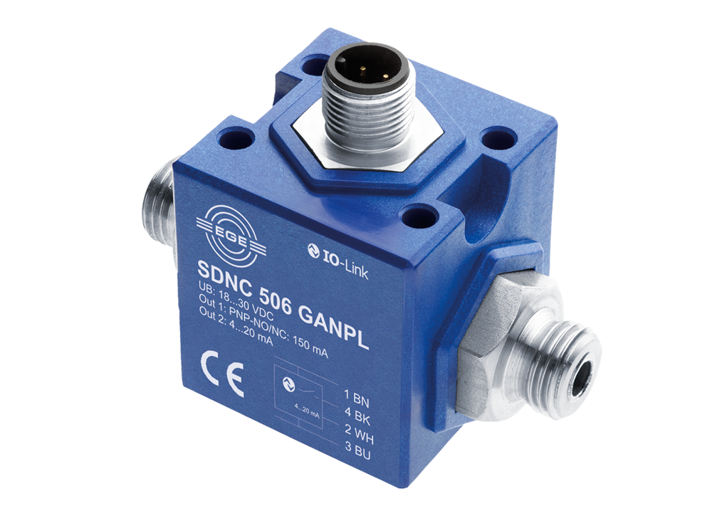
Sensors of the series SDNC... have a space-saving cubic design and opposing process connections with a G1/4 thread. They have a wide detection range and are sometimes operated with a screw-on pre-adapter or a straight inlet section providing a favourable flow profile for the flow rate detection.
This device series has been preconfigured at factory or can be supplied flexibly parametrisable using an IO link. This design also offers a pulse output for simple volume detection.